CAD & BIM
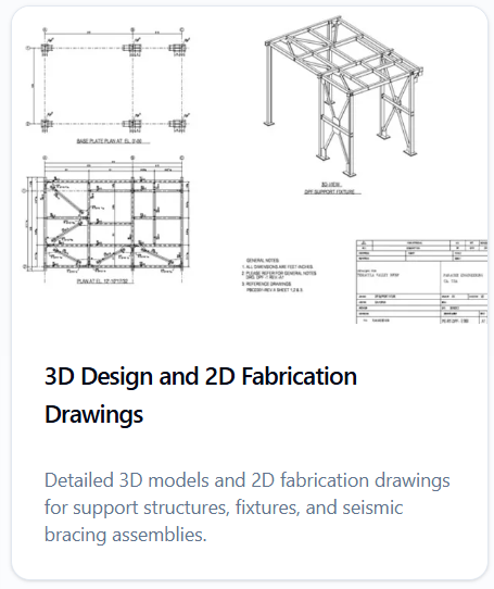
3D Design & 2D Fabrication Drawings
Detailed 3D models and issued-for-fabrication 2D shop drawings for equipment support structures, custom fixtures, and seismic bracing assemblies. SolidWorks, Tekla Structures, and AutoCAD workflows compliant with AISC 360-22, AWS D1.1, and ASME Y14.5 — PE/SE stamped on request.
- SolidWorks
- Tekla Structures
- AutoCAD
- Inventor
- Revit
- STEP / IFC
Software stack
We pick the platform to fit the geometry, the fabricator, and the downstream analysis pipeline — never the other way around.
Parametric solid modeling for equipment skids, custom fixtures, brackets, and weldments. Sheet-metal, weldment, and surface environments with full GD&T (ASME Y14.5) and Toolbox standard hardware. Used for tight-tolerance machined and welded assemblies.
- Top-down weldment assemblies with cut-list and BOM
- ASME Y14.5 GD&T on detail drawings
- Sheet-metal flat patterns for laser/waterjet/plasma cutting
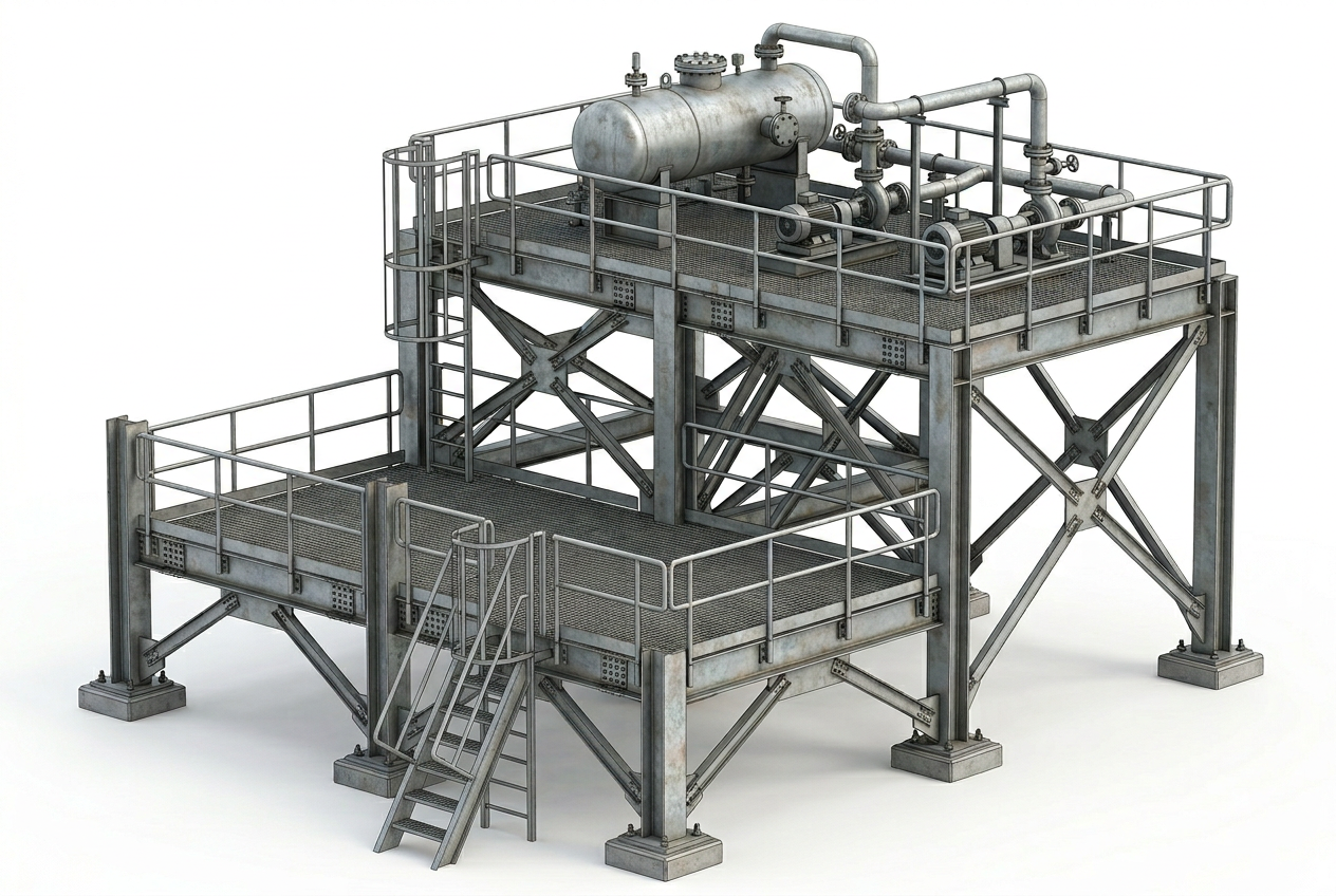
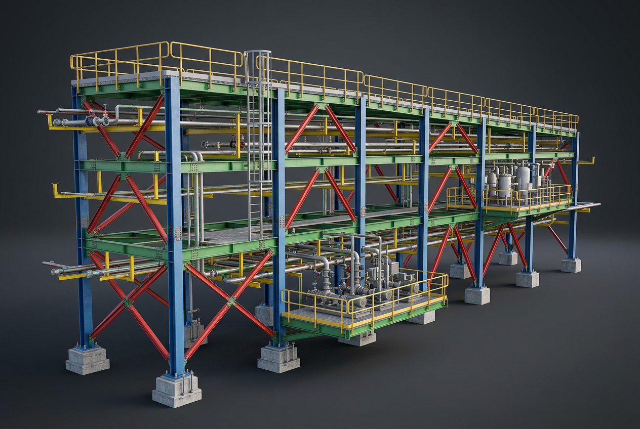
BIM-grade structural steel detailing for pipe racks, equipment platforms, mezzanines, and seismic bracing systems. Connection design, full clash detection, and IFC export for coordination with mechanical, electrical, and piping models.
- AISC 360-22 connections (CIDECT, CISC, BCSA modules)
- CNC NC1 / DSTV output for fabrication shop machinery
- IFC 4 / NWD export for BIM coordination
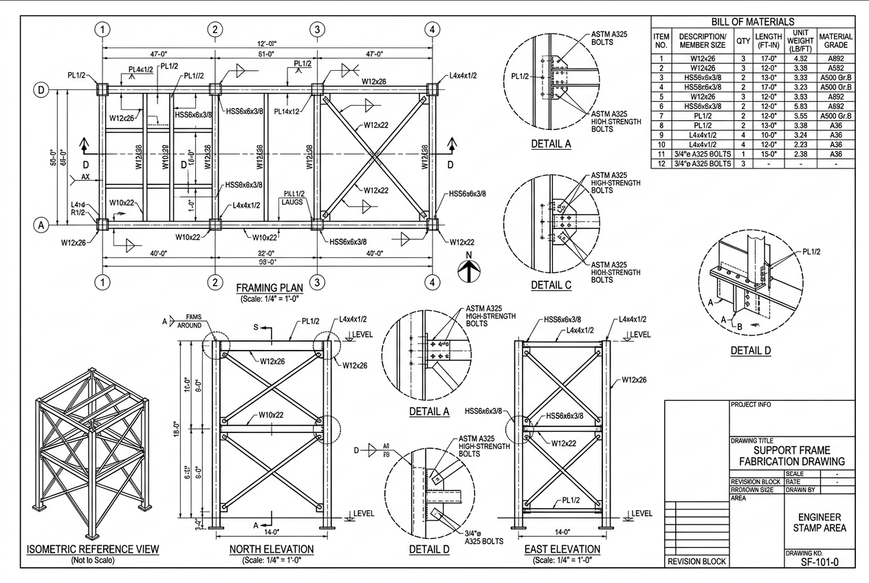
Industry-standard 2D fabrication shop drawings — base plate plans, member elevations, bracing layouts, weld and bolt details, and erection drawings. AWS A2.4 weld symbols, AISC detailing conventions, and ANSI title blocks ready for fabricator and AHJ review.
- AWS A2.4 weld symbols and AISC bolt callouts
- Layered drawings (S-, M-, E-) for trade coordination
- PDF, DWG, and DXF deliverables
Project requirements drive software selection. We also model in Autodesk Inventor for OEM equipment, Revit for architectural-coordinated MEP supports, and Siemens NX for advanced freeform geometry feeding directly into ANSYS Workbench.
- Inventor weldments and iLogic configurators
- Revit families for MEP support coordination
- STEP / IGES / Parasolid neutral-format exchange
From 3D model to fabrication
A single coordinated dataset drives the 3D assembly, BIM coordination model, and 2D shop drawings — eliminating inconsistencies between design intent and shipped steel.
Drawing types we produce
Every package is structured around AISC 303-22 Code of Standard Practice and the fabricator's preferred shop conventions.
Plan, elevation, and section views establishing overall geometry, member sizes, grid lines, and elevations. The reference document for all downstream details.
Field assembly drawings showing piece marks, bolt patterns, splice locations, and erection sequence. Coordinated with the structural engineer's loading and bracing requirements.
Single-piece details with cut lengths, hole patterns, bevels, weld preparation, and AWS-compliant weld symbols. Each piece tagged with a unique mark number tied to the BOM.
Anchor layout, projection, embedment, and tolerance plans coordinated with concrete rebar drawings. Includes ACI 318-19 Ch. 17 anchorage forces and template details.
Moment, braced, shear, and base-plate connections designed per AISC 360-22 and AISC Manual 16th edition. CBFEM verification (IDEA StatiCa) on demand for non-prequalified geometries.
Trapeze, transverse, and longitudinal bracing for piping, ductwork, conduit, and cable tray per ASCE 7-22 §13 and OSHPD OSP/OPM. Pre-approval drawings ready for AHJ review.
Deliverables
- 3D parametric model (SolidWorks .SLDASM, Tekla .db1, or neutral STEP/IFC)
- 2D fabrication shop drawings — plans, elevations, sections, and details
- Welded connection details per AWS D1.1 with AWS A2.4 symbology
- Bolted connection details per AISC 360-22 (slip-critical / bearing)
- Bill of Materials (BOM) with ASTM material grades and finishes
- Anchor bolt setting plans coordinated with concrete reinforcement
- CNC-ready DSTV / DXF / NC1 files for shop machinery
- PE / SE stamped drawing set on request (CA, NV, AZ, TX, FL, NY)
Standards & codes
- AISC 360-22 — Specification for Structural Steel Buildings
- AISC 303-22 — Code of Standard Practice for Steel Buildings and Bridges
- AWS D1.1 / D1.6 — Structural Welding Code (Steel / Stainless Steel)
- AWS A2.4 — Standard Symbols for Welding, Brazing, and NDE
- ASME Y14.5 — Dimensioning and Tolerancing (GD&T)
- ASME Y14.100 — Engineering Drawing Practices
- ACI 318-19 Ch. 17 — Anchoring to Concrete
- ASCE 7-22 §13 / §15 — Seismic design forces for components and non-building structures
Frequently asked questions
Need a fabrication-ready drawing package?
Send us your equipment cut-sheet, layout, or 3D scan — we will return a coordinated SolidWorks/Tekla model and a stamped AutoCAD shop drawing set ready for the fabricator and AHJ.