NFPA 13 §18.5 • ASCE 7-22 §13.3 • AISC 360 • HCAI/OSHPD
Seismic Bracing Calculations
The complete reference for sway brace design — NFPA 13 §18.5.9 sprinkler loads, ASCE 7-22 §13.3 horizontal demand, slenderness checks, zone-of-influence method, and worked examples for sprinkler risers, hydronic mains, and HVAC duct.
On this page
- ASCE 7-22 §13.3 horizontal seismic demand (Fp)
- NFPA 13 §18.5.9 sway brace load (Fpw)
- Seismic coefficient Cp table
- Zone of influence method
- Slenderness check (l/r ≤ 300)
- Brace angle & geometry
- Worked example 1: 6″ sprinkler main
- Worked example 2: 4″ hydronic chilled water
- Worked example 3: 36″ × 24″ HVAC duct
- Riser bracing (four-way)
- Brace anchorage to structure
- Common calculation mistakes
Section 1
ASCE 7-22 §13.3 — horizontal demand Fp
ASCE 7-22 governs all nonstructural component bracing in the IBC and CBC. The base equation for horizontal seismic force is:
bounded by:
Variable definitions
- • ap — component amplification factor (Table 13.6-1): 1.0 for rigid components (fp > 16.7 Hz), 2.5 for flexible
- • Rp — component response modification factor: 1.5 (low-deformability), 3.0 (limited-deformability), 6.0 (high-deformability)
- • SDS — design spectral acceleration at short periods (from USGS, site-specific)
- • Wp — operating weight of component including contents (water, refrigerant, fittings)
- • z/h — height ratio: 0 at grade, 1.0 at roof level
- • Ip — component importance factor: 1.0 standard, 1.5 hospitals/life-safety/Risk Cat IV
For most distribution piping, ap = 2.5 and Rp = 6.0 (high-deformability steel pipe). Plug those in:
Fp = 0.167 · SDS · Wp · (1 + 2z/h) · Ip
Section 2
NFPA 13 §18.5.9 — sprinkler sway brace load Fpw
For fire sprinkler systems, NFPA 13 supersedes ASCE 7-22 §13.6.5. The NFPA method is simpler and uses a single seismic coefficient:
- • Fpw — horizontal seismic load on the brace (lb)
- • Cp — seismic coefficient from NFPA 13 Table 18.5.9.3 (function of Ss)
- • Wp — weight of water-filled pipe + fittings + valves in the zone of influence (lb)
The 15% allowance for branch lines (§18.5.9.3.1) is built into the Wp calculation when the mainline is being braced.
Section 3
Seismic coefficient Cp table
From NFPA 13 Table 18.5.9.3 (interpolation permitted):
| Mapped Ss (g) | Cp | Typical regions |
|---|---|---|
| ≤ 0.50 | 0.40 | Texas, Florida, Midwest |
| 0.75 | 0.50 | Southeast, Mid-Atlantic |
| 1.00 | 0.60 | Sacramento, Portland |
| 1.25 | 0.70 | San Diego, Salt Lake City |
| 1.50 | 0.80 | Los Angeles basin, Bay Area inland |
| ≥ 1.74 | 1.00 | San Francisco, Oakland, Seattle |
Section 4
Zone of influence method
The zone of influence (ZOI) is the length of pipe tributary to a single brace. For a transverse brace spaced at maximum 40 ft along a 6″ steel main:
Wp per ft (6″ Sch 40, water-filled) = 31.7 lb/ft (pipe) + 14.7 lb/ft (water) = 46.4 lb/ft
Wp in zone = 46.4 × 40 = 1,856 lb (mainline only)
+ 15% branch allowance = 2,134 lb
Add the weight of any in-line valves, flanges, and unbraced branches that fall within the ZOI. The total Wp goes into both the NFPA Fpw and ASCE Fp formulas.
Section 5
Slenderness check (l/r ≤ 300)
Per NFPA 13 §9.3.5.10.4 and AISC 360, brace members in compression are limited:
l / r ≤ 200 (primary compression member)
Typical r values (least radius of gyration)
- • 1″ Sch 40 pipe: r = 0.421 in → max l = 126 in (10.5 ft)
- • 1¼″ Sch 40 pipe: r = 0.540 in → max l = 162 in (13.5 ft)
- • 1½″ Sch 40 pipe: r = 0.623 in → max l = 187 in (15.6 ft)
- • 2″ Sch 40 pipe: r = 0.787 in → max l = 236 in (19.7 ft)
- • L2×2×¼ angle: rz = 0.391 in → max l = 117 in (9.75 ft)
Cable braces are tension-only; slenderness does not apply, but the cable must be installed within its listed angle range and pre-tensioned to manufacturer spec.
Section 6
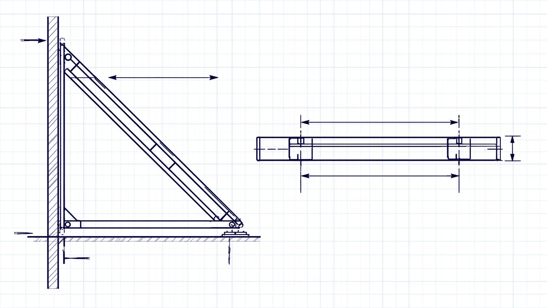
Brace angle & geometry
The brace angle θ measured from vertical determines the load split between the brace member and its anchorage:
Vertical anchor reaction: V = Fp · cot θ = Fp / tan θ
Allowable range: 30° ≤ θ ≤ 60° (NFPA 13 §18.5.5.6)
- • θ = 30°: Fbrace = 2.0·Fp, V = 1.73·Fp (high anchor uplift)
- • θ = 45°: Fbrace = 1.41·Fp, V = 1.0·Fp (balanced — preferred)
- • θ = 60°: Fbrace = 1.15·Fp, V = 0.58·Fp (high horizontal at base)
Worked Example 1
6″ sprinkler main, Los Angeles hospital
Pipe: 6″ Sch 40 black steel, water-filled, sprinkler main
Location: Los Angeles, Ss = 1.50g, SDS = 1.00g
Building: Hospital, Risk Cat IV, Ip = 1.5
Elevation: Roof level (z/h = 1.0)
Brace spacing: 40 ft transverse
Brace angle: 45° from vertical
Step 1 — tributary weight Wp
Wp = 33.71 × 40 ft × 1.15 (branch allowance) = 1,551 lb
Step 2 — NFPA 13 sway brace load Fpw
Fpw = 0.80 × 1,551 = 1,241 lb (NFPA 13)
Step 3 — ASCE 7-22 cross-check Fp
Fp = 258.5 × 3.0 × 1.5 = 1,163 lb
Lower bound: 0.3 × 1.00 × 1.5 × 1,551 = 698 lb ✓
Upper bound: 1.6 × 1.00 × 1.5 × 1,551 = 3,722 lb ✓
→ design for governing F = max(Fpw, Fp) = 1,241 lb
Step 4 — brace member sizing (45°)
Try 1½″ Sch 40 pipe — A = 0.799 in², Fy = 36 ksi
Brace length l = 48 in (typical)
Slenderness: l/r = 48 / 0.623 = 77 ≤ 300 ✓
Pn per AISC E3 ≈ 21.6 kips ≫ 1.76 kips ✓
Use 1½″ Sch 40 pipe brace — selection passes.
Step 5 — anchorage to concrete deck
Tu = V at anchor = 1,241 lb × 2.0 = 2,482 lb tension
Vu = 1,241 lb × 2.0 = 2,482 lb shear
Specify ½″ Hilti HIT-HY 200 V3 with HIT-Z rod, 4¾″ embed → ESR-3187 capacity OK
Worked Example 2
4″ chilled water main, Bay Area office
Pipe: 4″ Sch 40 black steel, water-filled hydronic
Location: Oakland, SDS = 1.50g
Building: Risk Cat II, Ip = 1.0 (not life-safety)
Elevation: Mid-height (z/h = 0.5)
Brace spacing: 40 ft transverse
Fp calculation (ASCE 7-22 §13.6.5 — non-sprinkler)
Wp = 16.3 × 40 = 652 lb (no branch allowance — non-sprinkler)
Fp = (0.4 × 2.5 × 1.50 × 652 / 6.0) × (1 + 2·0.5) × 1.0
Fp = 163 × 2.0 × 1.0 = 326 lb
Lower bound: 0.3 × 1.50 × 1.0 × 652 = 293 lb ✓
Design F = 326 lb per transverse brace.
Notice the dramatic difference: same pipe size, 1.5× higher SDS, but the sprinkler example governed by NFPA 13 was 3.8× higher because of the Ip = 1.5 multiplier and roof-level z/h.
Worked Example 3
36″ × 24″ HVAC duct (ASCE 7-22 §13.6.6)
Duct: 36″ × 24″ galvanized supply duct, 22 ga
Cross-section: 6.0 ft² (at threshold per §13.6.6)
Weight: ~22 lb/ft including insulation
Location: Sacramento, SDS = 0.80g
Building: Risk Cat III school (DSA), Ip = 1.5
Brace spacing: 30 ft transverse, 60 ft longitudinal
Fp calculation
Fp = (0.4 × 2.5 × 0.80 × 660 / 6.0) × (1 + 2·0.7) × 1.5
Fp = 88 × 2.4 × 1.5 = 317 lb
Lower bound: 0.3 × 0.80 × 1.5 × 660 = 238 lb ✓
Design F = 317 lb per transverse brace.
For ductwork the SMACNA Seismic Restraint Manual provides pre-engineered tables organized by SDS and Ip — verify that the SMACNA table's assumed SDS meets or exceeds the project value before using it.
Section 10
Riser bracing (NFPA 13 §18.5.9.4)
Sprinkler risers carry the full water column and require four-way bracing— restraint in both horizontal directions:
- • At the top of every riser, within 24 in.
- • At every floor in multi-story buildings
- • At any point where the riser passes through a floor or roof slab
- • Two transverse + two longitudinal braces, OR a listed four-way riser clamp (Tolco Fig. 980, etc.)
- • Apply Fp separately in each principal direction; do not combine the two directions on a single brace
Riser load calculation
Wp = 33.71 lb/ft × (riser height + 40 ft of branch) = full system tributary
Fpw = Cp × Wp applied to each four-way brace
Each direction designed for the full Fpw — not divided by 2
Section 11
Brace anchorage to structure
The brace member almost always passes — the failure mode is the connection at the structural attachment. Per ASCE 7-22 §13.4.2:
Vu = Ω0p · Fp · cos θ (anchor shear)
Ω0p = 2.0 for non-ductile concrete-controlled limit states
Verify the §17.8 tension-shear interaction at every brace anchor. For full ACI 318-19 Chapter 17 procedure, see our anchor bolt design examples page.
Section 12
Common calculation mistakes
- • Forgetting the Ip = 1.5 multiplier on hospital/school/Risk Cat IV projects — this alone can underestimate demand by 50%
- • Using empty-pipe weight instead of water-filled weight on sprinkler/hydronic systems
- • Skipping the 15% branch allowance on sprinkler mainline brace Wp
- • Using SMACNA tables without checking the table's assumed SDS against project
- • Applying brace angle outside 30°–60° range (geometry forces an inefficient or invalid brace)
- • Designing four-way risers with Fp/2 per direction — each direction must carry the full Fp
- • Ignoring Ω0p = 2.0 amplification on concrete-controlled anchorage limit states
- • Using the lower bound 0.3·SDS·Ip·Wp as the design force when the calculated Fp is higher
- • Skipping longitudinal bracing at change-of-direction fittings
- • Trapeze hangers used as both gravity support and seismic brace without combined-load check
Need stamped bracing calculations?
We deliver PE/SE stamped seismic bracing calculation packages for HCAI/OSHPD, DSA, and IBC plan check across all 50 states. Send your pipe/duct schedules and SDS — fixed-fee proposal in 48 hours.