ASCE 7-22 §13.6 • NFPA 13 • IBC/CBC • HCAI/OSHPD
Seismic Bracing Design for MEP Distribution Systems
PE/SE stamped seismic bracing design and submittal services for piping, ductwork, conduit, cable tray, and sprinkler systems. Code-compliant under ASCE 7-22 §13.6, IBC/CBC, NFPA 13, and HCAI/OSHPD — from threshold evaluation to stamped layouts to plan-check response.
What is seismic bracing?
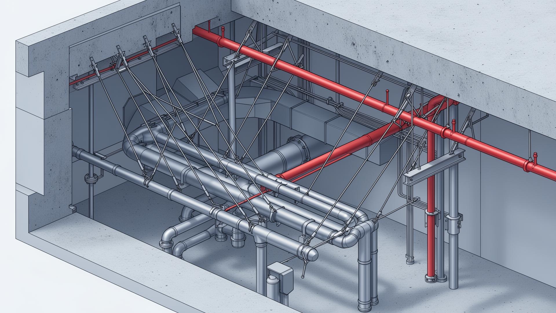
Seismic bracing restrains nonstructural distribution systems — piping, ductwork, conduit, cable tray, and sprinklers — against lateral and longitudinal earthquake forces. Unlike equipment anchorage (which fastens a single component to its base), bracing is a distributed system: each run requires periodic transverse and longitudinal braces sized for the seismic demand at that location.
Under ASCE 7-22 §13.6.5–13.6.7, bracing is required when threshold sizes are exceeded, hanger lengths exceed 12 inches, or the component importance factor Ip = 1.5. For California hospitals under HCAI/OSHPD, all distribution systems are typically braced regardless of size.
New to ASCE 7-22 §13.6? Read our companion technical guide: Seismic Bracing for Distribution Systems — covers thresholds, longitudinal vs transverse spacing, MSS SP-58 / SMACNA guidance, and hospital-specific Ip = 1.5 rules.
Common bracing failures we see
- • Pre-engineered cable braces installed beyond their listed angle range (30°–60° from vertical)
- • Missing longitudinal bracing at change-of-direction fittings
- • Brace anchorage into deck flutes without proper supplementary plates
- • Trapeze hangers used as both gravity support and seismic brace without verification
- • NFPA 13 sprinkler bracing not coordinated with adjacent ASCE 7 utilities
- • Hanger drops >12 in. without lateral bracing or rigid struts
Distribution systems we brace
Full ASCE 7-22 Chapter 13 coverage across mechanical, electrical, plumbing, and fire protection systems.
- Domestic water, hydronic, and process piping
- Medical gas (oxygen, vacuum, nitrous)
- Steam, condensate, and high-temperature piping
- Hazardous fluid piping (Risk Category IV)
- MSS SP-58 / SP-127 hanger and support compliance
- Supply, return, and exhaust HVAC ductwork
- Smoke control and pressurization ducts
- Lab fume and biosafety exhaust
- SMACNA Seismic Restraint Manual application
- Cross-sectional area thresholds (>6 ft²)
- Electrical conduit runs >2.5 in trade size
- Cable tray and ladder rack systems
- Bus duct and busway
- Emergency power and life-safety circuits
- Trapeze support seismic qualification
- Sway bracing per NFPA 13 §18.5
- Four-way bracing at risers
- Zone of influence calculations
- Coordination with adjacent ASCE 7 bracing
- Hospital and high-rise sprinkler bracing
What we deliver
End-to-end seismic bracing services from code-threshold evaluation to stamped construction documents.
PE/SE stamped seismic bracing layouts for piping, ductwork, conduit, cable tray, and sprinklers per ASCE 7-22 §13.6, IBC/CBC, and NFPA 13.
Specification, modification, and stamped sign-off of Hilti, Tolco, Mason, ISAT, and Eaton B-Line pre-engineered cable and rigid brace assemblies.
Bracing details and calculations packaged for HCAI plan check, including OPM, OSP coordination, and PIN 68 alignment for distribution systems.
Bracing modeled in Revit and Navisworks alongside MEP, structural, and architectural systems to eliminate field conflicts before installation.
Bracing Calculations
Seismic bracing calculation formulas
The same formulas we use on every PE/SE stamped bracing package — ASCE 7-22 §13.3 horizontal demand, NFPA 13 §18.5.9 sway brace loads, and AISC slenderness checks. Want a worked example? See our full calculations guide.
ASCE 7-22 §13.3 — horizontal seismic demand
bounded by 0.3·SDS·Ip·Wp ≤ Fp ≤ 1.6·SDS·Ip·Wp
- • ap = component amplification (1.0 rigid, 2.5 flexible)
- • Rp = component response modification (1.5–6.0)
- • z/h = ratio of attachment height to roof height
- • Ip = 1.0 standard, 1.5 hospital/life-safety
- • Wp = tributary weight (pipe + contents + fittings)
NFPA 13 §18.5.9.3 — sprinkler sway brace load
Cp per NFPA 13 Table 18.5.9.3 (function of Ss)
- • Cp = 0.40 (Ss ≤ 0.50g) up to 1.00 (Ss ≥ 1.74g)
- • Wp = weight of water-filled pipe + fittings + valves in zone
- • Includes 15% allowance for branch lines per §18.5.9.3.1
- • Brace, anchor, and structural attachment all sized for Fpw
- • Apply Ω0p = 2.0 on anchorage to concrete
Brace member slenderness — AISC 360 / NFPA 13 §9.3.5.10.4
l / r ≤ 200 (primary compression member)
- • l = unbraced length of brace member (in)
- • r = least radius of gyration of cross-section (in)
- • Schedule 40 pipe, angles, channels — all checked at installation angle
- • Cable braces are tension-only; slenderness does not apply
Brace orientation & angle limits
Horizontal brace force = Fp / sin θ
- • Outside 30°–60° → brace inefficient or geometrically infeasible
- • 45° is optimal — equal load split between brace and anchor
- • At 30°, brace force = 2× horizontal demand
- • Pre-engineered cable systems (Tolco, Mason) tabulate by angle range
Need worked examples? Our seismic bracing calculations guide walks through complete sprinkler riser, hydronic main, and HVAC duct brace designs with NFPA 13 + ASCE 7-22 numbers side by side.
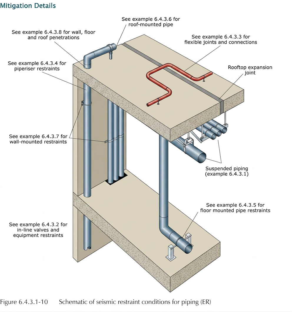
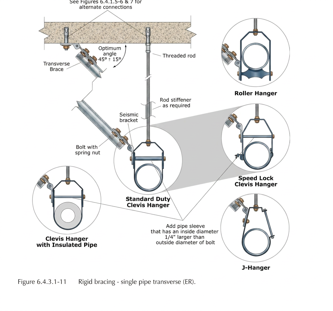
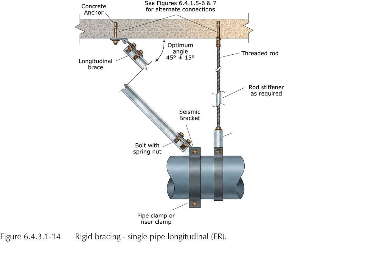
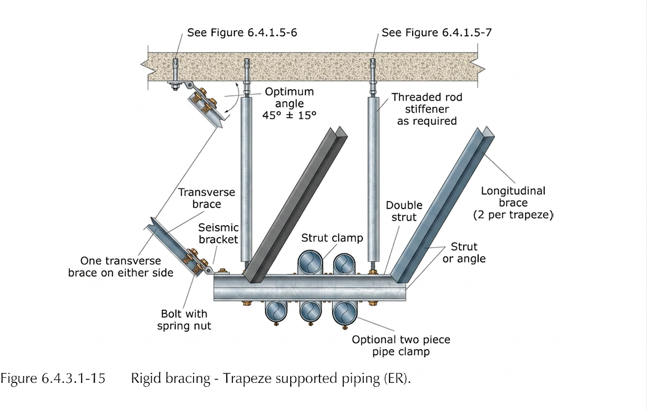
Pipe bracing details — FEMA E-74 reference figures
The four canonical brace configurations our PE/SE-stamped designs are built around. Reproduced from FEMA E-74 §6.4.3.1 (public domain).
Four-way riser bracing (NFPA 13 §18.5.9.4)
- • Required at the top of every sprinkler riser
- • Required at every floor in multi-story buildings
- • Located within 24 in. of the top of the riser
- • Resists motion in all four horizontal directions
- • Two transverse + two longitudinal braces, or a U-bolt riser clamp listed for four-way restraint
- • Apply Fp separately in each principal direction; do not combine
Branch line restraint (NFPA 13 §18.5.10)
- • Branch lines ≥ 2½″ require sway bracing same as mains
- • Branch lines < 2½″ may use wire restraints (12-gauge, 4-wraps)
- • Maximum unrestrained length: 30 ft for 1″ pipe, decreasing with size
- • End-of-line sprinklers within 24 in. of branch end need an additional restraint
- • Restraints attach to structural deck, not to ceiling grid or other utilities
- • Wire restraints: 45° ± 22.5° from vertical, opposing pairs
Transverse brace spacing
- • Maximum 40 ft on-center along main run
- • Within 20 ft of an unbraced end
- • Within 2 ft of any change of direction > 45°
- • Both sides of a flexible coupling or expansion joint
- • Brace force perpendicular to pipe axis
Longitudinal brace spacing
- • Maximum 80 ft on-center along main run
- • Within 40 ft of an unbraced end
- • Required on every straight run > 12 ft long
- • A transverse brace on a perpendicular branch counts as longitudinal for the parent run
- • Brace force parallel to pipe axis
California Hospitals
HCAI/OSHPD seismic bracing submittals
Hospitals and California Risk Category IV facilities trigger Ip = 1.5 for all life-safety and post-earthquake operability systems — meaning every distribution run is braced, regardless of size. Our HCAI submittal packages integrate bracing details with equipment anchorage (PIN 68), OSP pre-approval coordination, and PE/SE stamped calculations formatted for HCAI plan check.
Bracing standards & references
- ASCE 7-22 §13.6Seismic design requirements for nonstructural distribution systems
- IBC / CBCInternational & California Building Code MEP bracing requirements
- NFPA 13Standard for the Installation of Sprinkler Systems (seismic bracing)
- MSS SP-58 / SP-127Pipe hangers, supports, and seismic bracing standards
- SMACNASeismic Restraint Manual: Guidelines for Mechanical Systems
- HCAI/OSHPDCalifornia hospital seismic certification (OPM, OSP, PIN 68)
Frequently asked questions
Common questions on bracing thresholds, pre-engineered systems, sprinkler coordination, and HCAI requirements.
When is seismic bracing required for piping, ductwork, and conduit?
Under ASCE 7-22 §13.6.5–13.6.7, seismic bracing is required when the component importance factor I_p = 1.5, when distribution systems exceed threshold sizes (e.g., piping >2.5 in NPS in high-seismic areas, ductwork cross-sectional area >6 ft², conduit >2.5 in trade size), or when the supporting hanger length exceeds 12 inches. Hospitals (HCAI/OSHPD) and Risk Category IV facilities almost always trigger I_p = 1.5 and full bracing requirements.
What is the difference between transverse and longitudinal bracing?
Transverse braces resist lateral seismic forces perpendicular to the pipe/duct/conduit run. Longitudinal braces resist forces parallel to the run. ASCE 7-22 §13.6 requires both: typical spacing is transverse braces every 40 ft and longitudinal braces every 80 ft for piping, with closer spacing at changes of direction, branch connections, and equipment terminations.
Are pre-engineered seismic bracing systems (Hilti, Tolco, Mason) acceptable?
Yes — pre-engineered cable and rigid bracing systems from manufacturers like Hilti, Tolco, Mason Industries, ISAT, and Eaton B-Line are widely used and accepted by AHJs when installed within their listed seismic load capacities and spacing tables. Our team specifies, modifies, and PE-stamps these systems for project-specific demand, including OSHPD/HCAI submittals where pre-engineered listings alone are not sufficient.
Do sprinkler pipes follow the same bracing rules as other piping?
No. Fire sprinkler systems follow NFPA 13, which has its own seismic bracing requirements (zone of influence, sway brace spacing, four-way bracing at risers). ASCE 7-22 §13.6.5 explicitly defers to NFPA 13 for sprinklers. Our designs coordinate NFPA 13 sprinkler bracing with ASCE 7 bracing for adjacent mechanical and electrical distribution to avoid conflicts.
What additional seismic bracing requirements apply to California hospitals (HCAI/OSHPD)?
HCAI/OSHPD projects require all distribution systems to be designed for I_p = 1.5 with full transverse and longitudinal bracing, regardless of pipe size. Bracing details and calculations must be submitted with the OPM (Other Pre-approved Manufactured) or project-specific submittal. PIN 68 clarified equipment anchorage; bracing details for distribution systems must be PE/SE stamped and integrated with the equipment anchorage package.
Can BIM coordination reduce seismic bracing conflicts?
Yes. We model seismic bracing in Revit and Navisworks alongside MEP, structural, and architectural systems to identify and resolve conflicts before installation. Common clashes include brace cones overlapping ceiling grids, structural beams interfering with longitudinal brace runs, and parallel utilities sharing the same brace point. Early BIM coordination typically eliminates 60–80% of field RFIs related to bracing.
How do you calculate the seismic load on a sway brace?
Per NFPA 13 §18.5.9.3 (sprinklers) and ASCE 7-22 §13.3, the horizontal seismic load on a sway brace is Fpw = Cp × Wp, where Cp is the seismic coefficient (NFPA 13 Table 18.5.9.3, typically 0.4 to 1.0 depending on Ss) and Wp is the tributary weight of pipe + water + fittings within the brace's zone of influence. ASCE 7 calculates the equivalent demand as Fp = (0.4 × ap × SDS × Wp / Rp) × (1 + 2z/h) × Ip, with bounds 0.3·SDS·Ip·Wp ≤ Fp ≤ 1.6·SDS·Ip·Wp. The brace itself, anchorage, and structural attachment must each carry this demand with Ω0p amplification on concrete-controlled limit states.
What is the maximum slenderness ratio (l/r) for a seismic brace member?
Per NFPA 13 §9.3.5.10.4, brace members in compression shall have a maximum slenderness ratio l/r ≤ 300 unless designed as a tension-only cable system. ASCE 7-22 and AISC 360 follow the same KL/r ≤ 200 limit for primary compression members and ≤ 300 for secondary. Schedule 40 pipe braces, angles, and rods are sized so the unbraced length divided by the least radius of gyration stays below this limit; longer braces require larger sections or intermediate restraint.
Where are four-way braces required on sprinkler risers?
NFPA 13 §18.5.9.4 requires four-way bracing at the top of every sprinkler riser, at every floor in multi-story buildings, and at any point where the riser passes through a floor or roof slab. Four-way braces resist motion in all four horizontal directions (two transverse + two longitudinal). They must be installed within 24 inches of the top of the riser and at each intermediate floor support.
How is the zone of influence for a sway brace determined?
The zone of influence is the length of pipe (and any branches) tributary to a single brace, measured to the midpoint between adjacent braces or to a free end. For transverse braces with maximum 40 ft spacing, the zone is up to 40 ft of mainline plus all branch lines within that span that lack their own restraint. The total tributary weight (pipe + water + fittings + valves) within the zone is multiplied by Cp to get the brace design load.
Related services & resources
ASCE 7-22 §13.6 Bracing Guide (Blog)
Thresholds, transverse vs longitudinal, MSS SP-58 & SMACNA, hospital Ip = 1.5 rules.
Equipment Anchorage Design
ASCE 7-22 Ch. 13 anchorage for mechanical and electrical equipment.
HCAI/OSHPD Certifications
OSP, OPM, and OPA pre-approval submittals for California hospitals.
Shake Table Testing
ICC-ES AC156 qualification for active equipment requiring testing.
Seismic Anchor Calculations
ASCE 7-22 Chapter 13 anchor design library and worked examples.
All Engineering Services
Full suite of seismic and structural engineering capabilities.
Need PE/SE stamped seismic bracing?
Send your project scope — pipe/duct/conduit schedules, building Risk Category, and Sds — and we'll return a fixed-fee proposal within 48 hours.